Traffic Light LEDs Program in IoT: A Complete Code

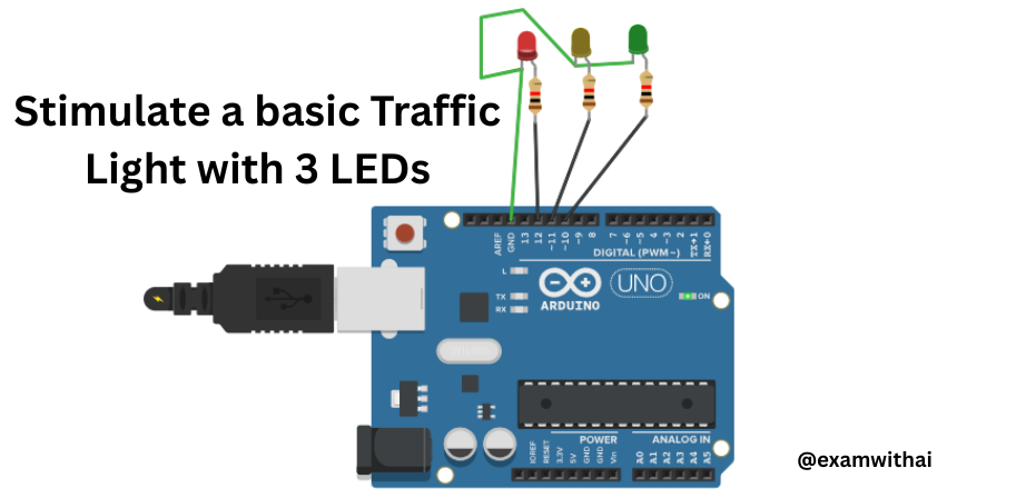
Write a program to simulate a basic traffic light with three LEDs, and each LED’s wait time is 4 sec.
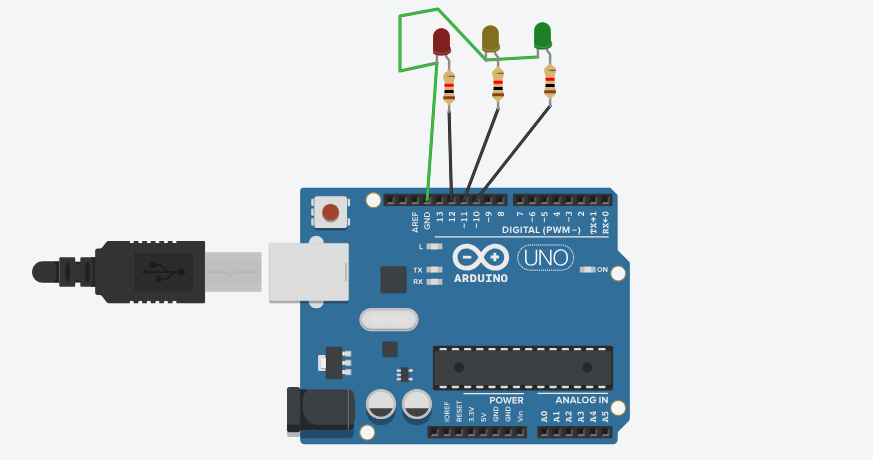
Traffic Light LEDs Program in IoT: This code simulates a traffic light system using three LEDs (red, yellow, and green) connected to pins 12, 11, and 10 on the Arduino board.
Function:setup()
void setup()
{
pinMode(12, OUTPUT); // Set pin 12 as an output (Red LED)
pinMode(11, OUTPUT); // Set pin 11 as an output (Yellow LED)
pinMode(10, OUTPUT); // Set pin 10 as an output (Green LED)
}- The
setup()function runs once when the Arduino starts. - It configures the pins 12, 11, and 10 to output mode so they can control LEDs.
Function: loop()
void loop()
{
digitalWrite(12, HIGH); // Turn ON Red LED (Pin 12)
delay(4000); // Wait for 4 seconds (4000 milliseconds)
digitalWrite(12, LOW); // Turn OFF Red LED
digitalWrite(11, HIGH); // Turn ON Yellow LED (Pin 11)
delay(4000); // Wait for 4 seconds
digitalWrite(11, LOW); // Turn OFF Yellow LED
digitalWrite(10, HIGH); // Turn ON Green LED (Pin 10)
delay(4000); // Wait for 4 seconds
digitalWrite(10, LOW); // Turn OFF Green LED
}
The loop()function runs continuously.
It turns on and off each LED in sequence, simulating the operation of a real traffic light.
- The red LED (pin 12) stays ON for 4 seconds.
- The yellow LED (pin 11) stays ON for 4 seconds.
- The green LED (pin 10) stays ON for 4 seconds.
After the green LED turns OFF, the loop starts again.
CODE
//Traffic LEDs
void setup()
{
pinMode(12,OUTPUT);
pinMode(11,OUTPUT);
pinMode(10,OUTPUT);
}
void loop()
{
digitalWrite(12,HIGH);
delay(4000);
digitalWrite(12,LOW);
digitalWrite(11,HIGH);
delay(4000);
digitalWrite(11,LOW);
digitalWrite(10,HIGH);
delay(4000);
digitalWrite(10,LOW);
}OUTPUT


